Museum News 2015
Museum News For 2015
Updated October 2015
February 2015
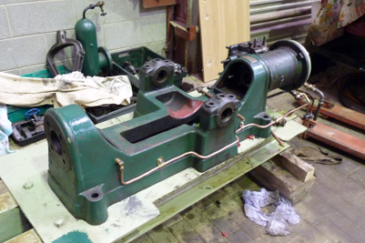
Joseph Evans Steam Pump - Update
Upon inspection, several parts were found to be in need of extensive repairs.
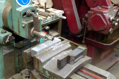
The piston rod, pump rod and eccentric rod all showed excessive wear. The only remedy is to machine new ones.
The main bearing (flywheel side) was in a poor state and badly worn. Work has started on machining a new one from Phosphor bronze.
Work has also started on machining a new part to replace the broken casting on the big end assembly.
New piston rings, for the water pump piston, have already been made to replace the worn ones.
June 2015
Clapham Beam Engine - Update
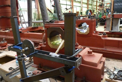
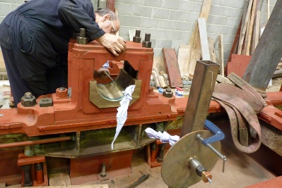
Now that the bottom half of the outer main bearing has been machined to the new crankshaft diameter, the bearing and its pedestal has to be aligned with the centre axis of the existing inner main bearing. The pedestal is mounted on an RSJ sub-frame, which can be adjusted for height by using jacking screws, built into the sub-frame. The lateral adjustment is by ‘skilful use of a large hammer.
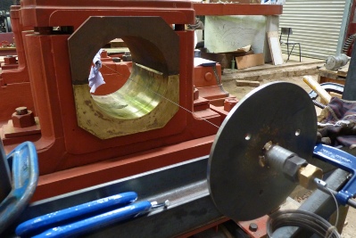
Sturdy steel frames were built and erected either side of the outer and inner bearing pedestals so that a taught piano wire (1mm diameter) could be stretched through the bearings to represent the centre of the crankshaft.
First the wire was adjusted so that it aligned exactly with the centre line axis of the existing inner main bearing on the main bedplate. This alignment was checked by measuring the distance from the wire to the bearing surface, using an internal micrometer. Once the wire was set in this way the centre line axis of the outer main bearing was adjusted, to the wire, by using the jacking screws on the RSJ sub-frame. Again the alignment was checked using an internal micrometer.
When the axes of the two bearings were set in line with each other, the position of the holding down bolt holes, on the outer bearing RSJ, had to be marked through to the main supporting RSJ frame. The whole of the outer bearing RSJ sub-frame was then moved to one side so that the holes could be drilled.
Once this was done the process of aligning the bearings to the piano wire had to be repeated. Substantial steel packing was inserted under the RSJ sub-frame (close to the holding down bolts), so that the whole weight was not resting only on the jacking screws. The whole outer bearing arrangement could then be finally bolted down in its correct position.
October2015
Clapham Beam Engine - Update
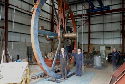
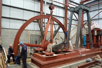
The outer and inner main bearings are now aligned ready to receive the crankshaft. The flywheel is in two halves and the outer rim joints are fastened by a tapered cotter arrangement. Lifting from the horizontal position would cause undue strain on these joints. With this in mind RSJ splints were strapped in place, across each joint, to give much needed support. The flywheel was then carefully slung and lifted vertical.
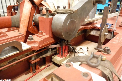
To lower the crank and flywheel assembly into the main bearings required accuracy and control, particularly on the inner main bearing, which requires the machined sides of the journal to fit snugly between the sides of the lower brass . Unfortunately, when lowering heavy objects with the overhead crane, there is very little control of the speed. A hydraulic jack was used, for the final part, to gradually lower the shaft into place.
With the flywheel and crank in place the next stage is to begin the process of bedding and scraping in the the brass bearings. This also means having to rotate the crankshaft and flywheel in a controlled manner. The crank itself causes an out of balance, so to overcome this, several plates were fastened to the flywheel rim, opposite the crank.
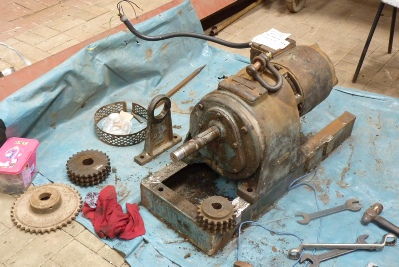
To rotate the flywheel a friction drive, through a rubber tyre on the rim, is to be employed. A reduction gear unit was rescued from the undergrowth outside and will be modified to provide the driving power.
The drive unit will eventually to used to bar over the engine for final restoration, maintenance and starting purposes..